Click
here to return to the PHY100F Homepage
PHY100F - THE MAGIC OF PHYSICS.
WAVES AND WAVE MOTION - a summary
General.
1. Waves come in a variety of types:
In this course we will deal mainly with travelling, periodic, transverse
waves.
2. For Periodic waves, we can define:
A : the amplitude (the maximum oscillation, measured from the
"zero" position).
 : the
wavelength (the distance in which the wave repeats itself)
f : the frequency (the number of oscillations in one second)
V : the speed (the length of the wave passing a given point
in one second)
I : the intensity of the wave (the amount of energy it carries).
Periodic waves come in many shapes and sizes - square, sinusoidal, sawtooth,
to name but a few.
3. Due to these definitions, there is a relationship between
wavelength, frequency and speed;
4. Since the speed of a wave in a given medium is constant, dependent
on the elastic constants (at a given temperature, pressure, etc.) of the
medium, this means that a wave with a low value of frequency has a long
wavelength, and vice-versa.
5. One of the most important features of waves arises because
of the Superposition Principle which states that the total effect of any
number of waves at a point is due to a simple algebraic sum (i.e. the sign
of the oscillation at that point has to be taken into account) of the individual
contributions from each wave arriving at that point. Due to this principle,
waves exhibit interference - examples are the double slit experiment, diffraction
of waves; also standing waves can be thought of as the sum of two travelling
waves going in opposite directions.
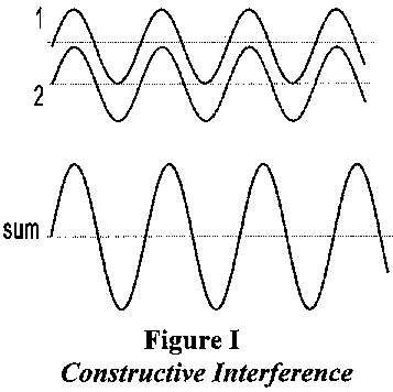
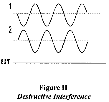
This means that waves can interfere with each other. An example
is given in Figure I : here the waves lie exactly on top of each other
and are said to be in phase - as a result their waves and troughs
add up to provide an example of constructive interference. In Figure
II however, the waves and troughs cancel each other out : the waves are
said to be out of phase, and in this case they exhibit destructive
interference so that their sum is zero.


The ability to interfere in this manner is an important signature
of waves.
6. The Intensity, I, of a wave is proportional to the
square of its amplitude; I = A2 .
7. When a wave encounters a physical object (e.g. an aperture
in a barrier, or a small obstacle in the path of the wave) its effect depends
on the relative size of the object d and the wavelength of the wave. (e.g.
when a wave passes through an aperture in a barrier, the diffraction, or
spreading out of the wave will be greater for small apertures). Specifically,
note that if the wavelength is much smaller than d (  <<
d ), wavelike behaviour (interference) will not be noticed. If however
the wavelength approaches d, interference effects will begin to
be observed. In fact, this effect sets the limit on the resolution of optical
instruments; for example, if two small objects are closer together than
a distance which is about the size of the wavelength used to observe them,
the interference effects make it hard or impossible to distinguish between
them.
Click here to return to top of document
THE NATURE OF LIGHT - the classical
view.
Isaac
Newton suggested that light, in view of its ability to travel in straight
lines and form sharp shadows round opaque objects, was corpuscular in nature.
This hypothesis, supported by Newton's authority and the lack of any contrary
evidence, held sway till the 19th century when improved measurements allowed
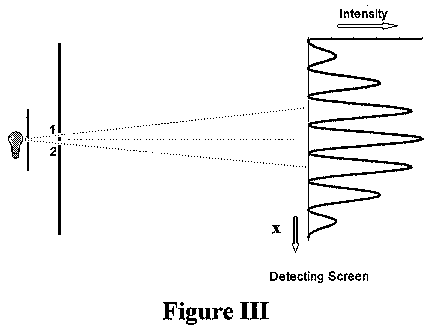
the observation of what appeared to be wave-like properties. The most famous
of these experiments was that of Thomas
Young. Young illuminated a pair of closely spaced slits in an opaque
screen with a monochromatic beam of light (light containing only one colour).
On another screen, placed at some distance away from the first, on the
other side of the light source, he observed interference fringes which
are the unmistakeable sign of a wave process (see Figure III).
Assuming that light was a wave, the simple classical theory of waves
could be used to give a complete description of the intensity distribution
of the interference pattern. The calculation of where the the maxima and
minima of this pattern should occur is so simple that it is worth repeating
here.
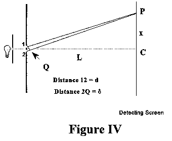
The argument is quite simple. Imagine that you were situated exactly
at the center of the detecting screen shown in Figure IV. If you
were to look back at the double slit system, the distance the two rays
from each slit would have to travel exactly the same distance to reach
you. They would thus arrive exactly in phase, and would add constructively.
If now you were to move a little to the side of the centre of the detecting
screen, one ray would have to travel a slightly longer distance than the
other to reach you. If the two distances from the slits differed by exactly
one half wavelength, the two light waves would arrive exactly out of phase
and would destructively interfere, so that you saw no light at that position
on the screen. As you moved further away from the centre of the screen,
the two rays would successively pass into and out of phase, and you would
see maxima and minima in the intensity pattern.


Click here to return to top of document
The Mathematics of the Interference of Light (optional!)
Assume that the wavelength of the light is  ,
the spacing between the slits in the first screen is d, and the
perpendicular distance between the two screens is L, as shown in
Figure III. For convenience the two slits are labelled as 1 and
2. Consider an arbitrary point, P, on the detecting screen.
Only if P were at the exact centre of the detecting screen would
the length of the light rays from slit 1 be exactly the same as
the length of the light ray arriving at P from slit 2. In
the general case, the lengths of these two light rays will be different.
Consider the case shown in Figure IV where the length of the ray
from slit 1 (call it 1) is less than the length of the
ray coming from slit 2 (call it 2). If, then, the difference
between these two lengths ( 2 - 1 ) is an exact number of wavelengths,
the effect of the two rays will add up - we say that they interfere constructively
- and we would expect a maximum of the light intensity. On the other hand,
if the difference in lengths ( 2 - 1 ) is an odd number of half
wavelengths, the two rays will cancel, or interfere destructively, and
we expect a minimum (zero) of light intensity reaching the point P. At
other places, where ( 2 - 1 ) lies between these two values, we
would expect intermediate values of intensity.
If we call the distance ( 2 - 1 ) = e,
we can express these conditions succintly (where n is an integer,
0,1,2,3,....) : if e = n , there will be a maximum at P: if e = {(2n +1) /2}
  =
(n + 1/2)
 ,
there will be a minimum at P. Thus the central maximum will occur
when e = 0 (at the centre of the detecting screen), the first zero
at e =
 /2,
the next maximum at e =
  ,
the next zero at e = 3
 /2, and so on. Now, in Figure II, let us draw in a perpendicular
line from slit 1 to the light ray from slit 2 to P;
let this line meet the line 2P in Q as shown. If the detecting
screen is sufficiently far away from the double slits, to a very good approximation
triangles 1CP, 2CP, and 1Q2, are similar (i.e. they have
the same shape). Therefore the ratios PC/L = 2Q/d ; but PC
is just x, the distance from the centre of the detecting screen
to the point P, and the distance 2Q is just the distance we have
defined above as e. Thus x = Le/d. But the different values
of e give us the positions of the zeroes and maxima of the interference
pattern observed on the detecting screen. Thus, for example, the first
zero is at x1 = Le/d = L
 /2d
; and the next zero is at x2 = Le/d = 3L
 /2d (substituting the values of e given above). So we can predict
exactly where the maxima and minima of the interference pattern will occur,
if we know the value of the wavelength of the light we are using.
Alternatively, knowing the dimensions of our apparatus,
we can calculate the wavelength of the light. For example, the distance
between the first two zeroes is given by (x2 - x1)
= 3L /2d - L /2d = L /d. So, knowing the values of the distances involved,
we can calculate the wavelength. It turns out that the wavelength of visible
light is in the range of 4x10⁻⁷ (violet) to 7.5x10⁻⁷ (red)
meters. In a similar, and almost as simple a fashion, the magnitude of
the intensity of light at each point on the detecting screen can be calculated;
that this simple assumption that light is a wave can yield such an accurate
description of observation goes a long way to assuring us that we are on
the right track.
Click here to return to top of document
![]() : the
wavelength (the distance in which the wave repeats itself)
: the
wavelength (the distance in which the wave repeats itself)


